OpenRM Demo Programs
This page has useful information about the demo programs that accompany the OpenRM-demo distribution. The OpenRM-demo distribution consists of a number of C source files, Makefiles, and a data directory with some sample data. The purpose of the demo programs is to provide you with some RM programming examples.
Table of Contents
- Building the Demos
- Running the Demos (Win32 and UNIX)
- The User Interface Model
- Data I/O Library
- Known Problems
- Info about Specific Demo Programs
- appTexturedPrims - application-supplied OpenGL texureIDs and display lists.
- autoTmap - application callback to use OpenGL's automatic texture coordinate generation tools.
- clipper - interactive clipping plane demo.
- clrball - concentric spheres with transparency.
- Cones - multibuffered/anaglyph stereo demo.
- dyntmap- dynamic texture mapping.
- elev - create a structured grid from scattered elevation samples.
- elev-2vu - Two Views of Elevation/Topography
- elevImage - RMimages and visualization colormaps (imaging)
- fogtest - interactive flythrough fogging demonstration
- fpsVis3d - report on rendering frame rate
- glxinfo - displays information about your X11 system.
- imgMirror - demonstration of imaging utilties to resize and mirror image data.
- indexedPrims2D - multiresolution rendering with indexed shape primitives.
- isodrv - build and display isosurfaces
- Jack - cones, cylinders and spheres.
- jballs - animation showing one ball orbiting another, the orbiting balls is a light source.
- keyfunc - Keyboard I/O Test
- 2D Lines - linestyles and widths in OpenRM
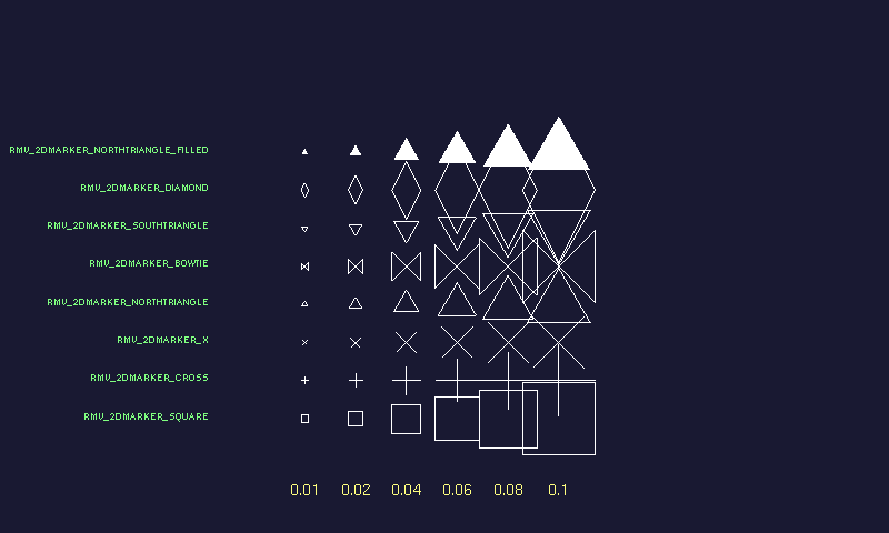
- markers2d - geometry-based glyphs
- Offscreen - offscreen rendering demonstration.
- ordertest - explicit sorted transparency
- pdb - Protein Data Bank Molecule Viewer
- pickTest - single object/primitive picking test
- pickListTest - reports on all objects under a given (x,y) pixel location
- pntcld - exercises features for OpenRM's point-based primitive
- Skeleton - a code skeleton for OpenRM applications
- spotlight - interactive spotlight control
- spriteTest - stress test for OpenRM's RMimage object manager.
- strands - textured, lit line segments
- tcube - multiple texture maps applied to a cube
- text2d - Text demo
- textureTest - stress test for OpenRM's texture object manager.
- tfly - a terrain flyover/visual simulation demo
- tmap2d - Two-dimensional texture mapping
- trans2d - Two-dimensional picking and translation
- vis2d - X-Y Plotting application
- vis3d - X-Y+ Plotting tool
- vrend - a hardware-accelerated, direct volume rendering application
- vslicer - cut arbitrary slices through a volume
- rm2screen - 2-window Tiled display with interactive transformations through a third, navigation window
- isodrv-mt - Threaded, parallel isosurfacer
Parallel/Multithreaded Demo Programs (UNIX only)
Building the Demos Under Win32
Posix Threads on Win32
Beginning with OpenRM version 1.4.0 and later, we rely on a third-party implementation of Posix threads in order to support multithreading. You will have to grab this library and install it in order to compile OpenRM on windows.
Visit the Posix Threads for Win32 website to grab the distribution. Please be sure to thank Ross Johnson for providing this invaluable library. If that site is busy, there is a mirror at the R3vis website. Refer to the OpenRM download page for the most current location.
Makefile.w32 Modifications
Inside Makefile.w32, the path to the OpenRM Scene Graph development libraries is set to /openrm/rm141. If you placed your RM Scene Graph distribution somewhere else, you must manually edit Makefile.w32 and change that path to reflect the actual location of OpenRM Scene Graph. After that, just type:
c:> nmake /f Makefile.w32
For a list of compilers used to build the RMSG distribution, please refer to the Release notes.
Running the Demos (Win32 and UNIX)
Each of the demo programs is designed to be run from the command line. Most of the demo programs have command line options that are used to specify input parameters. We've tried to document the complete set of command line parameters for each demo program below. However, if you forget, each of the demos will produce a "usage" line if an input parameter is bogus. All demo programs will behave intelligently if no input parameters are supplied.
All the demo programs will exit when you press the "q" key on the keyboard.
UI Model
Nearly all the RMdemo programs use the same user-interface model (with a couple of exceptions). We'll call this the "standard" UI model in the sections that follow (implemented using the combination of rmauxSetGeomTransform() and rmauxSetCamera3DTransform() call inside each demo program).
- No GUIs. There are no "quit" or "File->Read" buttons: all parameters are specified on the command line.
- To exit the demo programs in UNIX, press the "q" key on the keyboard. The program will exit.
- Rotations. On both Unix and Win32, press and drag with the middle button. This convention will cause problems on Win32 platforms that use a two-button mouse. If you prefer to map the rotations to a different button, you are free to modify the rmauxSetGeomTransform()routine in the file $RM151/rmaux/rmbfuncs.c.
- Isomorphic scaling. Press the Shift key, then press and drag with the middle mouse button. While dragging, as you move the cursor to the left, the object shrinks; as you move to the right, the object grows in size.
- Camera transformations (starting with v1.3.0). Camera control is implemented by rmauxSetCamera3DTransform(), and is comprised of two transformations: the camera can be translated parallel to the image plane, and the camera can be "dollied" along the Z axis in eye coordinates. All demo programs that are 3D use this camera transformation model. To translate the camera parallel to the image plane, press and drag with RM_BUTTON1 (the left button on my mouse). To dolly the camera along the Z axis in eye coordinates, press and drag with RM_BUTTON3; upward or downward motions will move the camera closer or farther away, respectively.
Nearly all of the 3D demo the demo programs start with this UI model as a base, then add additional actions as needed to exercise specific features exercised by the demo.
The Demo Programs
-
appTexturedPrims
-
autoTmap
-
clipper
- This program demonstrates two powerful OpenRM features: clipping planes and front-face/back-face drawing properties. The scene consists of a single sphere, a single clipping plane, and two light sources. The clipping plane is explicitly represented with a single quadrilateral. As the clipping plane is rotated (shift+button3), both the clip plane scene parameter and quad geometry are transformed. In order to avoid flimmering, the quad itself is placed into a different subtree of the scene graph so that it is not affected by the user-controlled clip plane.
- Command line usage: clipper [-w imageWidthInPixels] [-h imageHeightInPixels]
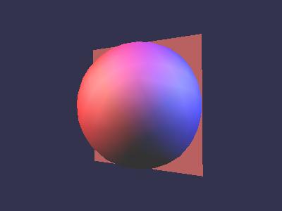
From one direction, the clipping plane appears as a filled quadrilateral. 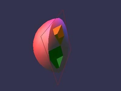
However, when it is rotated (shift+button3) to be seen from the opposite side, the back face is rendered in outline mode, and you can see what's inside the sphere. Clrball
- Uses the RMdemo "standard" UI model (above).
- Creates an image of two concentric spheres. The outer sphere is transparent. When you rotate both spheres, you will see artifacts caused by rendering of unsorted transparent polygons. This artifact is expected, but will be corrected in future versions of OpenRM when we implement sorted transparency algorithms.
- No command line arguments.
Cones
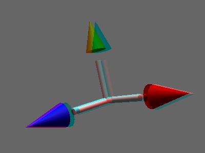
- Uses the RMdemo "standard" UI model (above).
- Builds a simple object from cones, cylinders and spheres. The application first tries to obtain a multibuffered stereo visual. If that fails, a warning message is issued, and then the application falls back to a red-blue anaglyph format. You'll need those funny red-blue paper glasses, put the red lens over the left eye. If you don't like that, and want the red lens over the right eye, edit the file cones.c and search for RM_REDBLUE_STEREO_CHANNEL. From there, the necessary change should be self-evident. Rebuild the program.
- Command line arguments.
- [-spin] (optional; when present, enables "auto-spin" mode. Default is no auto-spin mode.)
- [-fr NN] (optional; sets frame rendering rate to NN frames per second. NN should be a positive integer. Default is freely-running with no frame rate constraints.)
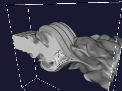
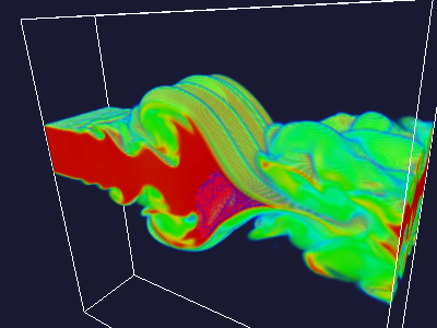
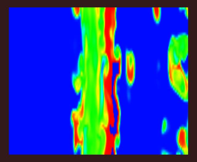
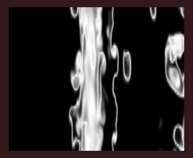
Dyntmap
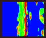
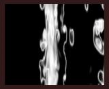
Dynamic texture mapping where the RMimage used in the RMtexture employ an RMvisMap containing a hue ramp in HSV space to highlight features in the source data (turbulence data courtesy the Center for Computational Sciences and Engineering, Lawrence Berkeley National Laboratory, Berkeley, CA). A grayscale RMvisMap. This demo program creates a single quad, and uses dynamic texture mapping to display volumetric data. The idle function will change the texture map to contain an RMimage created from the next slice of volume data.
- Command line arguments (all are optional)
   [-w display_window_width]
   [-h display_window_height]
   [-c (use default vis colormap to 'colorize' the plot')]
- Command line arguments (all are optional)
Elevation/Gridding
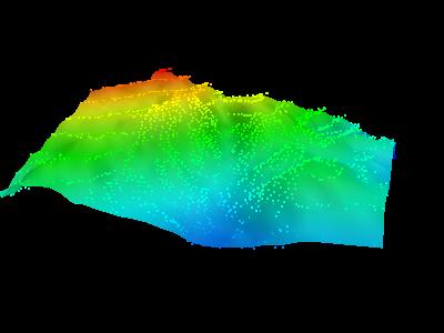
- Reads in some sample data from an ASCII data file, computes a surface from the data, generates geometry for the surface. The original sample points are represented using Point primitives. The data source was a summer student working at Lawrence Berkeley Laboratory who was playing around with a digitizing tablet and some topo maps.
- Command line arguments (all are optional):
- [-i datafilename] (defaults to data/elev.dio)
- [-w display_window_width] (sets pixel width of display window)
- [-h display_window_height] (sets pixel height of display window)
- [-c] (use default vis colormap to 'colorize' the plot')
- [-spin] (optional; when present, enables "auto-spin" mode. Default is no auto-spin mode.)
- [-fr NN] (optional; sets frame rendering rate to NN frames per second. NN should be a positive integer. Default is freely-running with no frame rate constraints.)
- Uses the RMdemo "standard" UI.
Two views of Elevation/Gridding
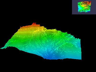
- Same as the "elev" program (above), but presents two views of the geom. Rotations are applied to the larger view only, while camera translations affect both views.
- Command line arguments (all are optional):
- [-i datafilename] (defaults to data/elev.dio).
- [-w display_window_width] (sets pixel width of display window).
- [-h display_window_height] (sets pixel height of display window).
- [-c] (use default vis colormap to 'colorize' the plot').
- Uses the RMdemo "standard" UI.
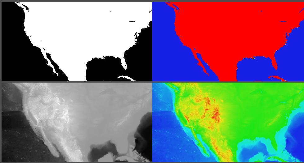
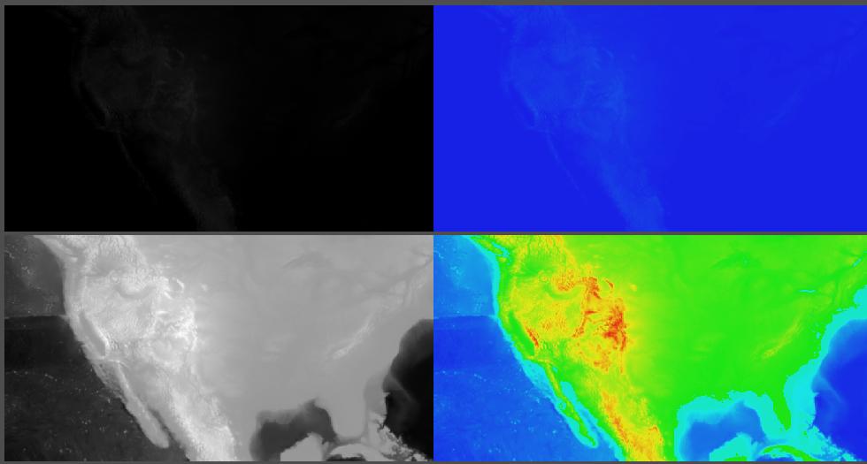
elevImage
RM_FLOAT pixel type RM_SHORT pixel type 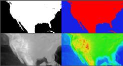
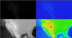
This demonstration program exercises several key OpenGL and RM imaging operators by manipulating raw digital elevation data in order to show different types of features. Pixel scale and bias parameters are used to remap the large dynamic range of the source data to known ranges. Visualization colormaps are used to reveal features within the raw data. Notes about the data, including the source, are available on this page.
- Command line arguments:
- "-f" use RM_FLOAT as the underlying pixel type (the default).
- "-s" use RM_SHORT as the underlying pixel type.
Referring to the left set of images, the following discussion applies to the use of RM_FLOAT as the pixel type. A similar sequence of steps is used when using RM_SHORT. This discussion was copied from the RM Programming Guide, Chapter 5, Images, Sprites and Bitmaps. The input data values range between -5650 and 3950, which represent elevation in meters below or above sea level.
The upper left image was created using the raw, or unmodified pixel values. As these floating point pixels move through the OpenGL imaging pipeline, they are clamped to the range 0.0 to 1.0, producing an image that is white where elevation values are greater than zero (higher than sea level), and black where negative.
To create the image on the upper right, a copy of the source image was created using rmImageDup(), then a default visualization colormap as assigned to the new RMimage. The default visualization colormap is a hue ramp, so small-valued pixels map to blue, and large-valued pixels map to red.
The images on the bottom row were created by creating duplicate RMimages of the top-row images, again using rmImageDup(). Scale and bias values were added to the images on the bottom row in order to evenly map the input range of pixel values to the output range.
The scale value used for both images in the bottom is identical, and is computed as follows: scaleValue=1.0/(dataMax-dataMin). This formulation has the effect of scaling pixels in the range {dataMin..dataMax} into the range {0.0 .. 1.0}. In order to translate the scaled pixel range into {0.0 .. 1.0}, we compute a bias value as follows: Bias = -dataMin/scaleValue.
- Interaction model:
- Press the "q" key to exit the program.
Fogtest
- Command line arguments (all are optional).
- [-w display_window_width] (sets the pixel width of the display window).
- [-h display_window_height] (sets the pixel height of the display window).
- [-fr NN] (optional; sets frame rendering rate to NN frames per second. NN should be a positive integer. Default is freely-running with no frame rate constraints.)
- Uses the "flight stick" user interface for navigation. See the description of tfly (below) for more information about the flight stick user interface.
- If you wish to change any of the fogging parameters, you will need to edit the fogtest.c source file, modify fogging parameters as desired, then recompile.
- Command line arguments (all are optional).
fpsVis3d
glxinfo - Displays GLX/OpenGL information about your system.
This handy program obtains and displays information about the GLX subsystem of your X server. It doesn't generate any interactive graphics, but does write detailed information to stdout. Here's an example:
OpenRM Scene Graph (v1.6.0), Copyright (C) 1999-2005, R3vis Corporation. OpenGL Details: vendor: NVIDIA Corporation version: 1.5.3 NVIDIA 76.67 renderer: Quadro4 750 XGL/AGP/SSE2 extensions: GL_ARB_depth_texture GL_ARB_imaging GL_ARB_multisample GL_ARB_multitexture GL_ARB_occlusion_query GL_ARB_point_parameters GL_ARB_point_sprite GL_ARB_shadow GL_ARB_shader_objects GL_ARB_shading_language_100 GL_ARB_texture_border_clamp GL_ARB_texture_compression GL_ARB_texture_cube_map GL_ARB_texture_env_add GL_ARB_texture_env_combine GL_ARB_texture_env_dot3 GL_ARB_texture_mirrored_repeat GL_ARB_texture_rectangle GL_ARB_transpose_matrix GL_ARB_vertex_buffer_object GL_ARB_vertex_program GL_ARB_vertex_shader GL_ARB_window_pos GL_S3_s3tc GL_EXT_texture_env_add GL_EXT_abgr GL_EXT_bgra GL_EXT_blend_color GL_EXT_blend_minmax GL_EXT_blend_subtract GL_EXT_compiled_vertex_array GL_EXT_Cg_shader GL_EXT_draw_range_elements GL_EXT_fog_coord GL_EXT_multi_draw_arrays GL_EXT_packed_pixels GL_EXT_paletted_texture GL_EXT_pixel_buffer_object GL_EXT_point_parameters GL_EXT_rescale_normal GL_EXT_secondary_color GL_EXT_separate_specular_color GL_EXT_shadow_funcs GL_EXT_shared_texture_palette GL_EXT_stencil_wrap GL_EXT_texture3D GL_EXT_texture_compression_s3tc GL_EXT_texture_cube_map GL_EXT_texture_edge_clamp GL_EXT_texture_env_combine GL_EXT_texture_env_dot3 GL_EXT_texture_filter_anisotropic GL_EXT_texture_lod GL_EXT_texture_lod_bias GL_EXT_texture_object GL_EXT_vertex_array GL_HP_occlusion_test GL_IBM_rasterpos_clip GL_IBM_texture_mirrored_repeat GL_KTX_buffer_region GL_NV_blend_square GL_NV_copy_depth_to_color GL_NV_depth_clamp GL_NV_fence GL_NV_fog_distance GL_NV_light_max_exponent GL_NV_multisample_filter_hint GL_NV_occlusion_query GL_NV_packed_depth_stencil GL_NV_pixel_data_range GL_NV_point_sprite GL_NV_register_combiners GL_NV_register_combiners2 GL_NV_texgen_reflection GL_NV_texture_compression_vtc GL_NV_texture_env_combine4 GL_NV_texture_rectangle GL_NV_texture_shader GL_NV_texture_shader2 GL_NV_texture_shader3 GL_NV_vertex_array_range GL_NV_vertex_array_range2 GL_NV_vertex_program GL_NV_vertex_program1_1 GL_SGIS_generate_mipmap GL_SGIS_multitexture GL_SGIS_texture_lod GL_SGIX_depth_texture GL_SGIX_shadow GL_SUN_slice_accum GLU Details: version: 1.3 extensions: GLU_EXT_nurbs_tessellator GLU_EXT_object_space_tess GLX Server Details: vendor: NVIDIA Corporation version: 1.3 extensions: GLX_EXT_visual_info GLX_EXT_visual_rating GLX_SGIX_fbconfig GLX_SGIX_pbuffer GLX_SGI_video_sync GLX_SGI_swap_control GLX_ARB_multisample GLX Client Details: vendor: NVIDIA Corporation version: 1.3 extensions: GLX_ARB_get_proc_address GLX_ARB_multisample GLX_EXT_visual_info GLX_EXT_visual_rating GLX_EXT_import_context GLX_SGI_video_sync GLX_NV_swap_group GLX_NV_video_out GLX_SGIX_fbconfig GLX_SGIX_pbuffer GLX_SGI_swap_control GLX_NV_float_buffer GLX_ARB_fbconfig_float-
imgMirror - demonstration of imaging utilties to resize and mirror image data
This demo reads in an image file, scales it to a smaller size, then creates 3 multiple copies of the image. Each copy is mirrored from the original, first about the vertical center, then the horizontal center, the both the vertical and horizontal centers. Each image is placed into a sprite primitive, and all four images are rendered.
- Uses no UI model; to quit, type the "q" on Unix or the "esc" key on Win32.
- Command line arguments: none.
- Note: this demo program requires that JPEG support be enabled in OpenRM, and will make use of the JPEG library to load the source raster file.
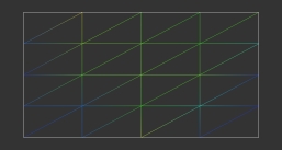
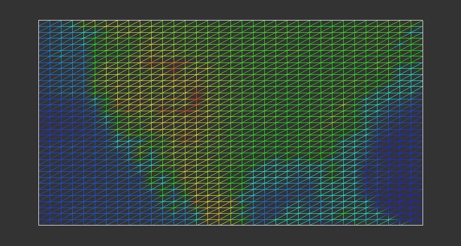
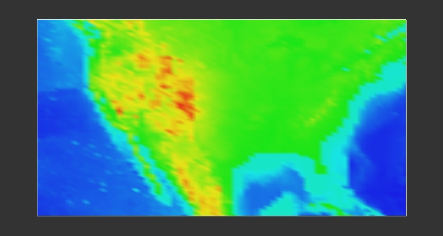
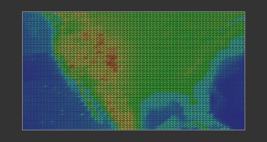
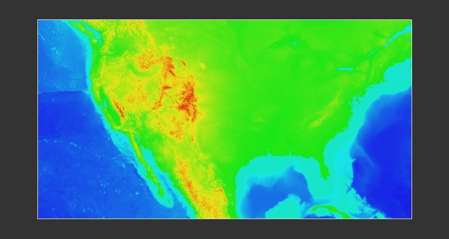
indexedPrims2D
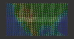
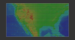
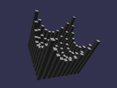
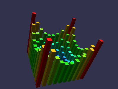
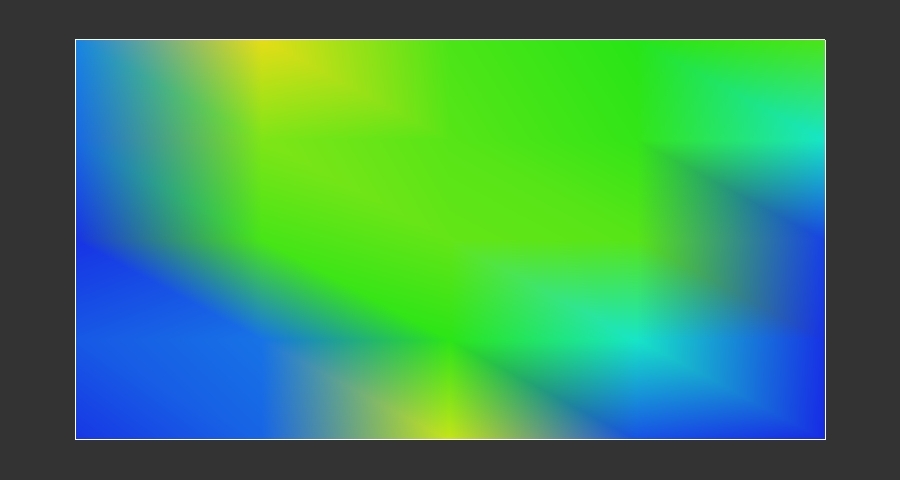
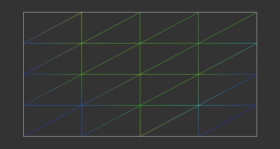
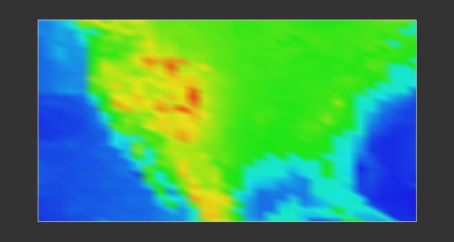
Demonstration of multiresolution rendering using "indexed" shape primitives. This appliction uses the same raw DTE data as the "elevImage" application, and constructs a 2D mesh where each vertex is color-coded according to the DTE value, where each represents elevation. The 2D mesh coordinates are inferred from the corners DTE grid corners, which represent a (latitude,longitude) coordinate.
When you start the application, it creates an RMprimitive of the named type where the number of vertices is equal to the full resolution of the DTE model (approximately 817 by 361 points). On the first frame, the RMprimitive's index array is computed so that the grid will be rendered using only three equidistant points along each axis, for a total of four quads, eight triangles, two t-strips or two q-meshes, depending upon the type of primitive requested from the command line. On each subsequent frame, the index array is recomputed to include on additional grid point along each axis. When the full resolution is reached after about 831 frames, the process begins again with a coarse representation. The application will "run freely" until you tell it to quit by typing a "q" on the keyboard.
Note that on each frame, only the index values are recomputed and inserted into the RMprimitive. The vertex and color values are loaded once at the beginning of the run and thereafter remain constant. This application shows how to use indexed primitives to achieve multiresolution rendering.
The panel of images below illustrate the evolution over time of the application. The first row shows the results after three frames, the second shows the results after 33 frames, the third is from the 66th frame, and the final row is from the 600th frame. The left column is rendered using filled indexed quads, while the right is rendered using outline indexed t-strips. You may specify primitive type and draw mode from the command line.
Command line arguments (all are optional).
- [-w imageWidthPixels] (Sets the width of the display window. The default is 900 pixels wide.)
- [-h imageHeightPixels] (Sets the height of the display window. The default is 480 pixels high.)
- [-prim ( iquads | itstrips | iqstrips | itris )] (Selects from one of four different indexed shape primitives. The default is iquads, or indexed quads.).
- [-draw ( fill | line | point ) (Selects the polygon rendering mode. Choose one of filled, outline only, or point-per-vertex rendering. The default is filled.)
Keyboard interface options. The only thing you can do with the keyboard is to tell the application to quit by typing a "q" key.


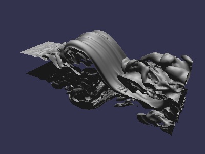
isodrv - Generating and viewing isosurfaces from w=f(x,y,z) data
This demo programs reads in a canned volume from the data directory, computes an isosurface, displays the resulting surface and lets you perform interactive transformations.
- Uses the RMdemo "standard" UI model.
- Command line arguments:
isodrv [-w img_width] [-h img_height] [-l isolevel]
- The isolevel parameter is a floating point number. The default value is 0.5. The input volume consists of unsigned bytes that are converted to 0..1.0 for the purposes of visualization.
NOTE: this program takes a while to run, anywhere from 10 seconds on a fast machine to upwards of a minute on a small Win32 box before any results are displayed on screen. It will consume a lot of resources and generates upwards of 300K triangles.
Jack
- UI model is the same as the cones demo.
- This program exercises OpenRM's internal OpenGL state tracking code.
-
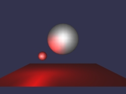
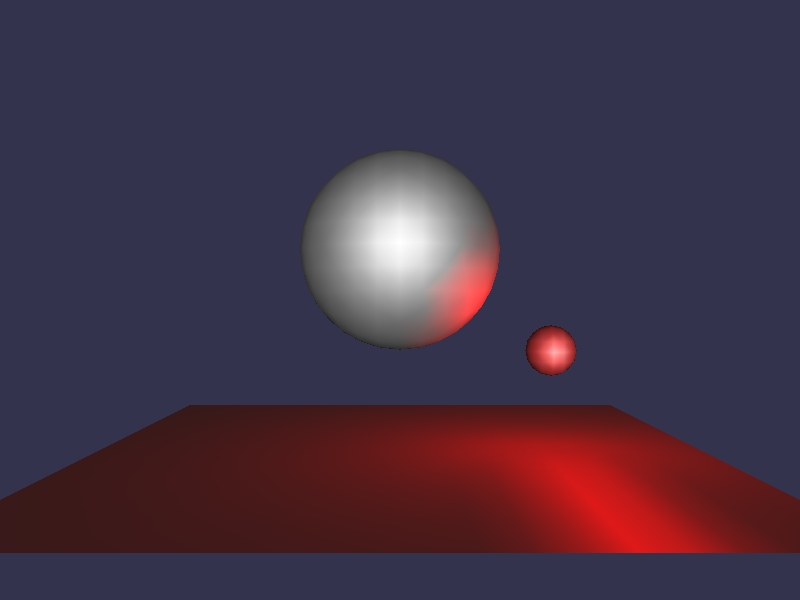
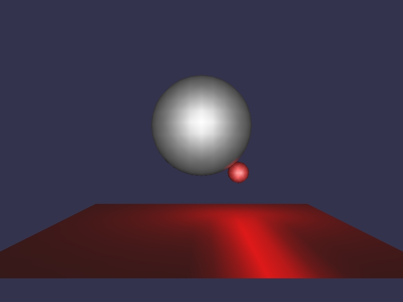
jballs - animation showing light source movement
Jballs was inspired by a demo program that comes with one of the Java developer kits, hence the name. Jballs generates an animation showing one sphere orbiting another. The smaller sphere, colored red, shows the location of a point light source that orbits the larger sphere. A second light source is positioned approximately at the same location as the viewer to create a "headlight" effect. The animation will run continuously until you tell it to stop by pressing the "q" key on the keyboard.
You can also interactively transform all objects using the RMdemo "standard UI" model.


-
keyfunc - interactive keyboard I/O demo
-
lines2D - sample of linestyles and widths in OpenRM
This program displays the five different OpenRM line dashing styles, in three different line widths, for a total of fifteen different line segments. There are no command line arguments to this program. The image below shows the screen display of lines2d.
-
markers2d - geometry-based glyphs
-
Offscreen - offscreen rendering demonstration
The "offscreen" program is a reimplementation of the isosurface demo, but rendering is performed into an offscreen buffer. After rendering, the framebuffer contents are written to a disk file, "offscreen.jpg". Offscreen rendering is supported in Unix/Linux/Win32.
-
orderTest - explicit sorted transparency
-
PDB - Protein Data Bank Molecule Viewer
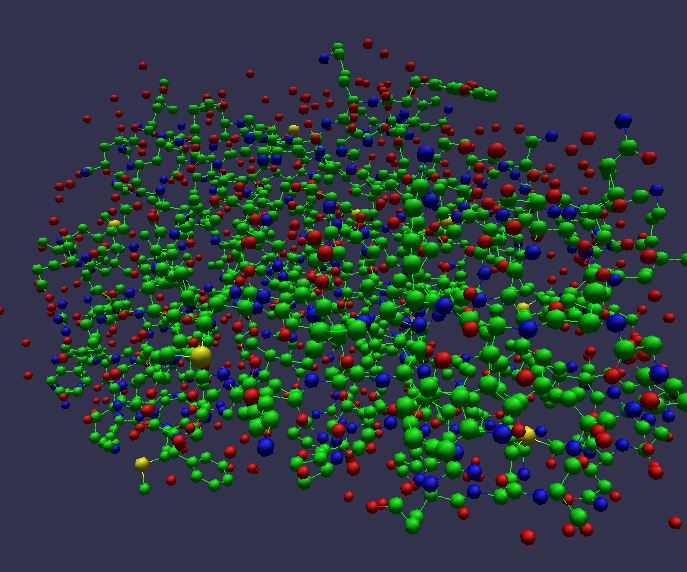
This demo reads in "PDB" files and displays them in ball-and-stick format. The underlying code that parses the PDB file has not been thoroughly tested, as it comes from other freely available software.
- Input files. By default, "pdb" reads in the file named "data/1a30.pdb" which is a derived model of the HIV-1 virus, and was obtained directly from the Protein Data Bank at the Research Collaboratory for Structural Bioinformatics.
- Uses RMdemo "standard" UI model, but with one interesting addition:
- Background color and depth image demonstation.
- In addition to displaying PDB files, this program is a testbed for the use of the combination of background image tiles and background depth images.
- The left button (both Win32 and Unix) is a toggle. When depressed (press then release, don't drag) for the first time, the depth and color buffers are read from the graphics device and stored into the RM scene graph as background depth image and background color image scene parameters. Then, use the Rotate button (Right mouse button in Win32, middle button in UNIX) to rotate the model. Only the line segments move. In fact, only the line segments are being rendered. The color and depth buffer from the image with the spheres remains static and is reused in each frame, thereby accelerating rendering using this simple image-based acceleration.
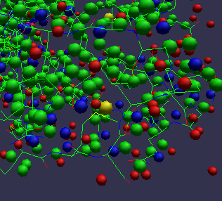
This close-up view shows how only the molecular bonds, shown as line segments, are transformed after toggling background image/depth-buffer mode. - In addition to displaying PDB files, this program is a testbed for the use of the combination of background image tiles and background depth images.
-
pickTest
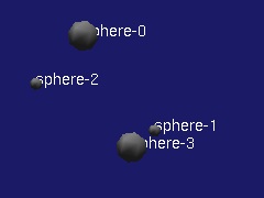
This demonstration program exercises picking in 3D. When you click on the left mouse button, the object closest to the viewer at the (x,y) location corresponding to the "hot spot" of the cursor is picked, then highlighted in yellow. The name of the picked object is displayed using rmNotice().
- Uses the RMdemo "standard" UI model.
- Pressing the left mouse button will initiate a pick operation. The object closest to the viewer at the "tip of the arrow" of the cursor will be picked, then highlighted. If you pick in the background, "all" objects are picked.
- Command line arguments:
 pickTest [-w img_width] [-h img_height] [-n numSpheres (default is 10,
  maximum is RM_COMPONENT_POOL_SIZE/2, which is about 1024 in v1.4.2) ]
-
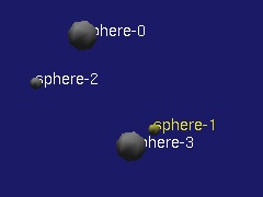
pickListTest
This demonstration program exercises picking in 3D. When you click on the left mouse button, the object closest to the viewer at the (x,y) location corresponding to the "hot spot" of the cursor is picked, then highlighted in yellow. The names of the all objects that intersect the (x,y) pixel location are displayed using rmNotice().
- Uses the RMdemo "standard" UI model.
- Pressing the left mouse button will initiate a pick operation. The object closest to the viewer at the "tip of the arrow" of the cursor will be picked, then highlighted. If you pick in the background, "all" objects are picked.
- Command line arguments:
 pickListTest [-w img_width] [-h img_height] [-n numSpheres (default is 10,
  maximum is RM_COMPONENT_POOL_SIZE/2, which is about 1024 in v1.4.2) ]
-
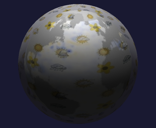
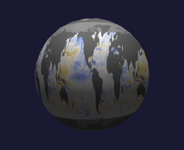
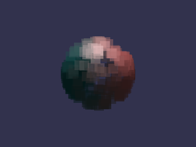
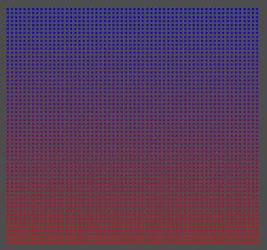
pntcld - exercises features for OpenRM's point-based primitive
Generates randomly positioned directed points that lie on the surface of a sphere. The closer to the "north pole" the points are located, the "more red" they become. Points in the southern hemisphere become more blue as they approach the south pole.
- Uses the RMdemo "standard" UI model.
- Command line arguments:
pntcld [-w img_width] [-h img_height] [-n num_points] [-s seed] [-p pointSizeInPixels] [-tc]
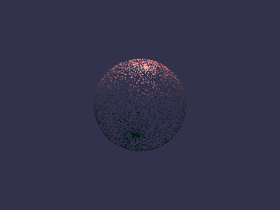
Command line: pntcld -n 4000 produces a total of 4000 points in a single point primitive. 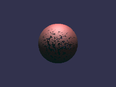
Command line: pntcld -n 4000 -p 5 produces a total of 4000 points in a single point primitive where each point is rendered as a 5x5 square. 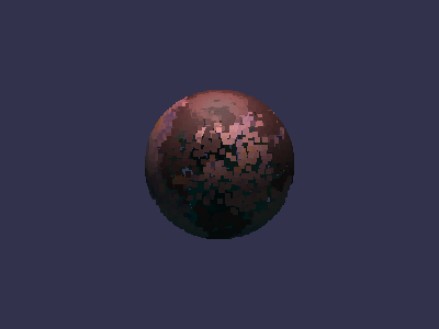
Command line: pntcld -n 4000 -p 5 -tc produces a total of 4000 points in a single point primitive where each point is rendered as a 5x5 square, and texture coordinates are generated for each point to sample a default image containing sea surface temperature. In this image, we're looking at the north Atlantic, with North America visible on the left side of the globe, while the westernmost portions of Europe and Africa appear along the right limb of the globe. -
Skeleton
The skeleton.c file contains a bare-bones (skeleton) framework that you can use to create your own OpenRM application. Most of the RMdemo programs are built using a similar code structure. This program will compile and run, but doesn't do anything interesting.
-
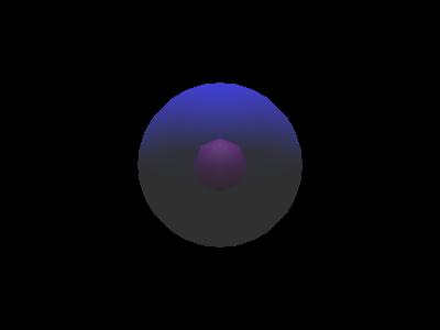
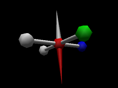
Spotlight
This demo program creates a scene consisting of five walls, a static point light source and a dynamic spotlight. You can use the middle mouse button to rotate the spotlight around in the scene. In addition, you can move the viewpoint around using the left or right mouse buttons. This program is different than the other RMdemo programs because rotations for the spotlight are harvested from RMaux using a dummy scene graph node. During each frame rendering call, the spotlight is recomputed using the then-current rotation matrix. To change the spotlight cutoff angle or light falloff exponent, you'll have to hack on the code, changing a couple of #defines at the top of the program.
- Command line arguments:
spotlight [-w imgWidth] [-h imgHeight]
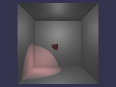
A window dump from the spotlight demo program. - Command line arguments:
-
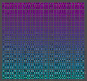
spriteTest - stress test for OpenRM's RMimage object manager.
The spriteTest program was created to exercise code that performs RMimage object reallocation inside the RM component manager and context cache. This program generates many, many sprite RMprimitives. Each RMsprite primitive consists of an RMimage object that is 8x8 pixels in size. The solid color used for each sprite is a function of the number of the sprite created by the application.
- Usage:
spriteTest [-w windowWidth] [-h windowHeight] [-n numSprites] [-p]
- The [-w windowWidth] and [-h windowHeight] arguments are optional. The default window size created by this program is 1024x960.
- The [-n numSprites] value is also optional, and controls the number of sprites that are generated. Inside spriteTest, a total of n by n sprites are generated, and the value numSprites specifies the square root of the number of sprites actually generated. The default value is 60, which means that a total of 3600 sprites are generated, arranged in a 60 x 60 array of sprites when rendered. If you specify a value of, say, 10 for this argument, a total of 100 sprites are generated and rendered in a 10x10 array of sprites.
- The [-p] argument will enable sprite picking. We used spriteTest with picking and large numbers of sprites to test the expanded pick limits added to OpenRM version 1.5.1.
- Use the "q" key to exit the program.
- Usage:
-
strands - textured, lit line segments
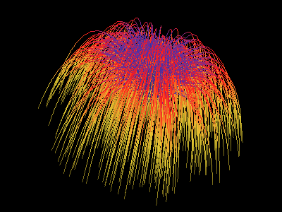
Command line: strands -n 1000 produces 1000 individual "strands". Each strand here is a line strip that has a 1-D texture coordinate assigned at each vertex to produce the colors. The source texture is a 4-color, one-dimensional "image". Color interpolation is performed by OpenGL at the pixel fragment stage of the rendering pipeline. 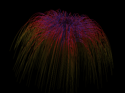
Command line: strands -n 1000 -l 1 same as above, but lighting is enabled via the addition of a normal at each vertex of the line strip. 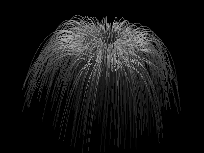
Command line: strands -n 1000 -l 1 -tc 0. While lighting is activated, no texture coordinates have been specified, nor are there any per-vertex colors. The result is that the "current color" is used, and the current color is white. The result is grayscale. -
tcube

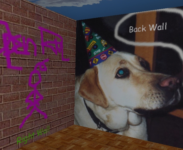
A window dump from the tcube demo program. This demo program uses six texture maps, each applied to a different face of a cube. Upon startup, you're looking at the cube from the outside. Use the interactive controls to translate the camera to the interior of the cube (right mouse), then rotate the room about your viewpoint to check out the artwork (middle mouse).
- Usage:
tcube [-w img_width] [-h img_height] - Uses the RMdemo "standard" UI model.
- Usage:
-
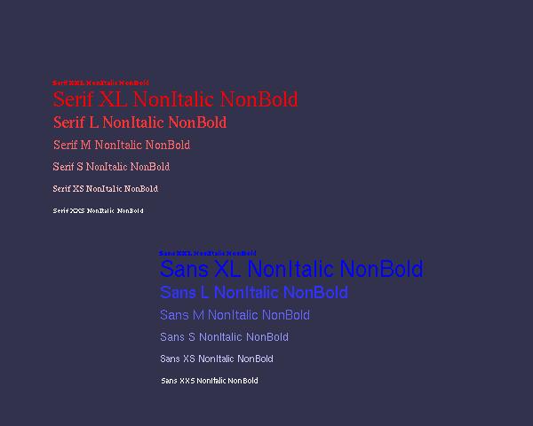
Text2D
Creates an image of a number of text strings in a number of differnent fonts, sizes and properties. The same RM-based code runs on both Win32 and UNIX. (!!!) This program has no command line arguments.
-
textureTest - stress test for OpenRM's texture object manager.
The textureTest program was created to exercise code that performs texture object reallocation inside the RM component manager and context cache. This program generates many, many textures mapped onto 2D quads. Each texture consists of a checkerboard image that is 8x4 pixels in size. The colors of the checkerboard are a function of the texture number created by the application.
- Usage:
textureTest [-w windowWidth] [-h windowHeight] [-n numTextures]
- The [-w windowWidth] and [-h windowHeight] arguments are optional. The default window size created by this program is 1024x960.
- The [-n numTextues] value is also optional, and controls the number of textures that are generated. Inside textureTest, a total of n by n textures are generated, and the value numTextures specifies the square root of the number of textures actually generated. The default value is 32, which means that a total of 1024 textures are generated, arranged in a 32 x 32 array of textured quads when rendered. If you specify a value of, say, 10 for this argument, a total of 100 textures are generated and rendered in a 10x10 array of textured quads.
- Use the "q" key to exit the program.
- Usage:
-
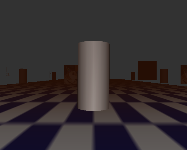
tfly: a visual simulation, terrain-flyover prototype
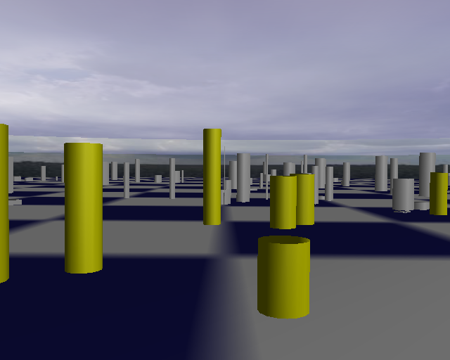
A window dump from the tfly demo program. 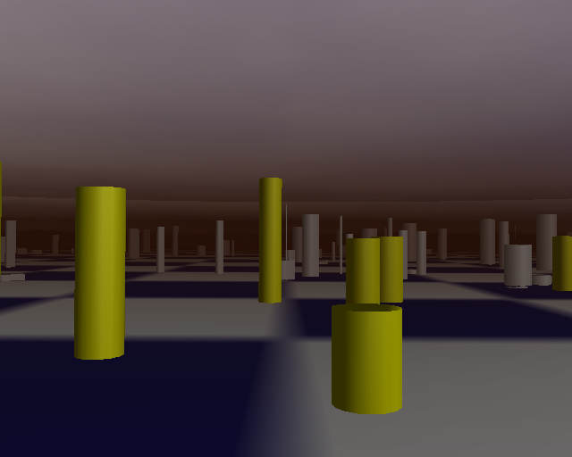
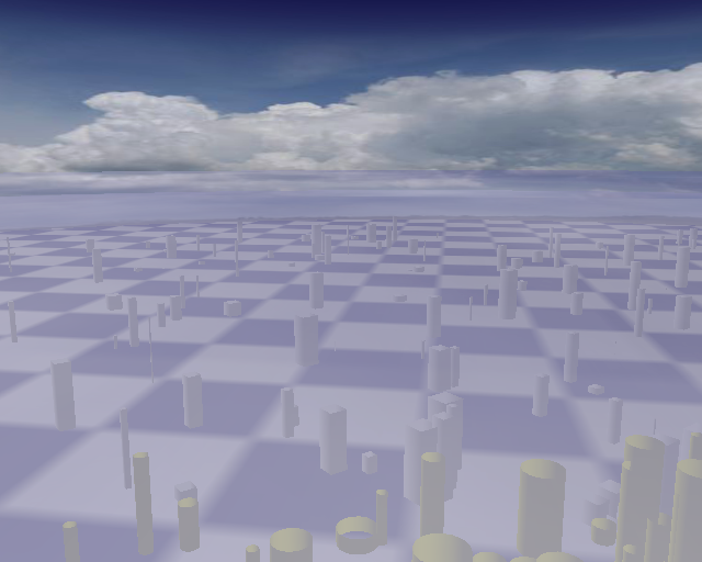
Beneath you is a checkered floor, above you, the clouds. You are in a small virtual world that contains a number of randomly placed and sized cylinders.
Tfly uses a "flight stick" model of navigation. Upon clicking the left mouse button, you will begin to fly through the scene. Changing the vertical position of the pointer will change camera pitch vector, and changing the horizontal position of the pointer will change camera roll vector. As you move forward through the scene, cylinders closer to you change color, and also resolution.
This demo program shows how to use node pretraversal callbacks to implement application-side view frustum culling, and view-dependent model switching (also known as level-of-detail).
- Uses the new rmauxFlyUI interface for terrain flyovers
- Optional use of RM interface to OpenGL fogging
- Command line arguments:
tfly [-w img_width] [-h img_height] [-f (to enable fogging)] [-fr NN (sets frame rate to NN frames per second)]
The default fogging mode is GL_LINEAR, as specified inside tfly.c. A recompile is required in order to modify any fogging parameters (this will change in future versions of the program).
On some modern architectures, tfly will generate frames at an astounding rate - upwards of 500fps!! To slow things down so you can actually navigate, use the -fr NN command line argument to set the frame rate. Try a value of 60 for starters: -fr 60.
-
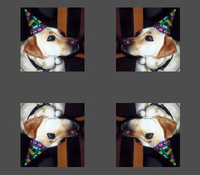
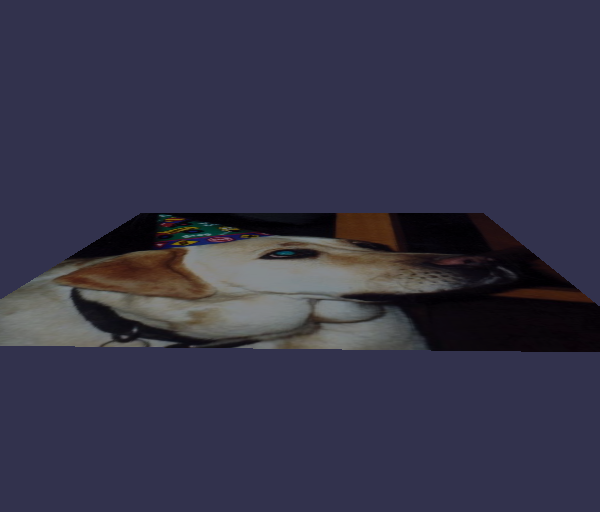
tmap2d - Two-dimensional texture mapping
Demonstrates how texture mapping is integrated into the RM scene graph model. This program reads in an image file, assigns the image as a texturing scene parameter at a node in the scene graph, then creates geometry with texture coordinates. When the program is first started, the demo program uses RM's hardware image-resize tool to make the image a size that is an even power of 2 (for OpenGL), then creates the model and renders it. The geometry is a plane that is parallel to the line of sight, so when the image is first rendered, it looks like an empty window. Rotate the object around with the mouse and it will become visible.
- Command line arguments. With no command line arguments, reads in
an image from the data directory, and texture maps that image onto
a single quad.
tmap2d [-w img_width] [-h img_height] [-mips (compute all mipmaps)] [-t prim_type (0=single quad, 1=disjoint tris, 2=t-strip, 3=t-fan)] [-i fname (name of avs image file to use as a texture)] - Uses the RMdemo "standard" UI model.
- Other images. You can instruct tmap2d to read in other images than the one of my dog at a birthday party, and they can be in one of PPM, JPEG or AVS image formats. As built, tmaps2d reads in a JPEG file. To read in a different file, you'll have to change the filename inside the code and recompile. To use one of the other formats (AVS, PPM), you'll have to change the call to use the appropriate file/image loader inside the code, and recompile.
- Command line arguments. With no command line arguments, reads in
an image from the data directory, and texture maps that image onto
a single quad.
-
Trans2D: Two-dimensional picking and translation
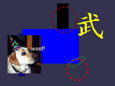
A collection of objects is created and placed at random locations within the window. Position the cursor over an object, click with the left mouse button and drag. The way this program works is to find the primitive picked by the user, then translate the RMnode containing that primitive around on the screen. Since some RMnodes contain more than one primitive, depending upon which object you pick, several objects may move around as a group. Also, note what happens when you pick "in the background."
The objects displayed include: a sprite primitive, a bitmap primitive, a 2d text primitive, some circles, ellipses and 2d boxes.
- Command line arguments
trans2d [-w xxx (image width)] [-h xxx (image height)]
- This program reads a couple of canned image files from the data directory, and will break if the data directory is not in the same directory as the trans2d executable.
- Command line arguments
-
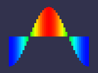
Vis2D: an X-Y Plotting tool
Exercises all of RM's tools in RMV that can be used to "visualize" 2D data of the form y=f(x). A canned data file is read from the data directory, run through a visualization tool, then the results are inserted into the scene graph then rendered.. There are actually several different sample data files in the data directory that can be used with vis2d.
- Command line arguments.
vis2d [-i datafilename (defaults to data/cos.dio)]
      [-w img_width] [-h img_height]
      [-v vis_technique (an integer in the range 0..8 that
          chooses a visualization technique..default is 0)]
      [-c (colorize the resulting geometry as a function of the data)]

- Command line arguments.
-
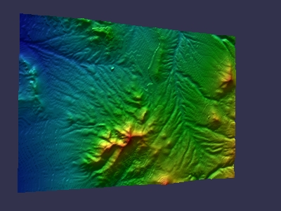
Vis3d: X-Y+ Plotting tool
Tool that visualizes 3D data of the form z=f(x,y). (Some would call that "2 1/2 D visualization," and we agree with that to some extent) Numerous visualization techniqes are supported, we invite you to play with the input parameters. Be sure to try out the file named data/topo256.dio with this program.
Also demonstrates the use of "the dynamic backstop" as well as the background image tile.
- Uses the RMdemo "standard" UI model.
- Command line arguments.
vis3d [-i datafilename (defaults to data/func10.dio)
      [-w img_width] [-h img_height]
      [-c (use default vis colormap to 'colorize' the plot')]
      [-v n (where n=0..11, and indicates which visualization technique to use)]
      [-bs (make a 'vanishing backstop')
      [-bg (tile the background with the AVS image data/orangegrid.x))]
      [-p (print the scene graph to stderr)]
-
Vrend: Example of Direct Volume Rendering
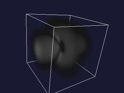
NOTE: this program works only on OpenGL implementations that support the 3D texturing extension. As such, this program WILL NOT WORK on Win32 systems. We hope that one day Microsoft will provide a version of OpenGL that is compliant with the 1.2 specification.
This program reads in a canned data file, and generates an RM_OCTMESH primitive, then produces images using a direct volume rendering technique. This demonstration will severely tax your graphics hardware. Those with software OpenGL will get at best one frame every 5 seconds. However, click button 1 (the left mouse button for most) to switch to "bounding box mode" for transformation. Click button 1 again to return to full resolution volume rendering.
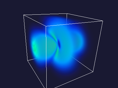
vrend [-w imageWidth] [-h imageHeight] [-c (colorize the volume)]
When the volume is colorized (with the -c option), a default RMvisMap is created. The default map is a hue ramp, ranging from blue (low values) through green and yellow (intermediate values) through red (high values). This demonstrates the use of RM's built-in use of the pixel transfer feature of the OpenGL imaging pipeline.
-
Vslicer: Example of Advanced use of 3D texture memory
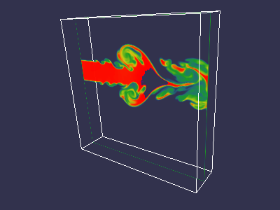
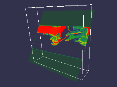
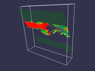
NOTE: this program works only on OpenGL implementations that support the 3D texturing extension. As such, this program WILL NOT WORK on Win32 systems. We hope that one day Microsoft will provide a version of OpenGL that is compliant with the 1.2 specification.
This demo program reads in a canned volume, optionally colorizing the data, then loads it into texture memory. A single quad object is created which may be interactively transformed by the user. The vslicer program rotates not only the single quad, but also manipulates (transforms) the texture coordinates via the OpenGL matrix stack. Applications are protected from the complexity and detail of the texture matrix stack manipulation is through the RM API.
vslicer [-w imageWidth] [-h imageHeight] [-c (colorize the volume)]
Button 2 rotates the bounding box and the quad together, but does not modify the texture coordinates of the quad. Use button 1 to rotate just the quad, and to reveal a different part of the volumetric data set. Note that anisomorphic scaling is required to make this "look right."
When the volume is colorized (with the -c option), a default RMvisMap is created. The default map is a hue ramp, ranging from blue (low values) through green and yellow (intermediate values) through red (high values). This demonstrates the use of RM's built-in use of the pixel transfer feature of the OpenGL imaging pipeline.


Parallel and Multithreaded Applications
As part of work funded under a Small Business Innovation Research (SBIR) grant from the U.S. Department of Energy, Office of Science during the period Sep 2000 through April 2001, OpenRM Scene Graph supports multithreaded applications via a "thread safe" scene graph implementation. The two demo applications included with OpenRM in RMdemo exercise two aspects of "thead safety": multiple scene graph readers and multiple scene graph writers. As of the time of this writing (July 15, 2001, updated January 2004), these programs are supported only under Unix implementations.
Win32 users that want to enable full multistage and multithreaded rendering of any other RMdemo programs may do so by modifying the file procmode.h, and changing the default processing mode from RM_PIPE_MULTISTAGE to either RM_PIPE_MULTISTAGE_PARALLEL or RM_PIPE_MULTISTAGE_VIEW_PARALLEL. We note that none of the RMdemo programs, with the possible exception if tfly really lend themselves to significant speedup by placing the view and render stages in separate threads. One does not expect significant speedup from such an architecture unless there is a signficant amount of model-level culling performed in the view stage, and none of the RMdemo programs, except possibly tfly have sufficiently complex models that become simplified during the view traversal.
-
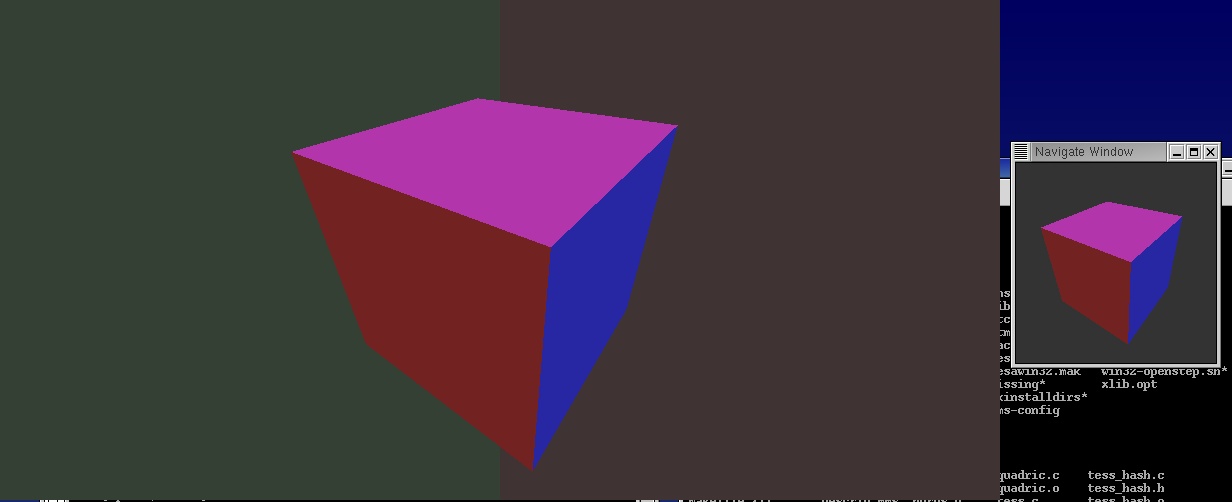
rm2screen - Tiled display example
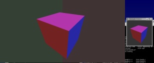
rm2screen is an example of a tiled-surface display application. It creates a total of 3 windows, one of which is a "master", and two of which are "slaves." The master window is controlled by the RMaux event loop driver - users can transform the object in the "navigate window" (the name of the master window), and the two slave windows are redrawn using the new transformation. rm2screen uses a sheared-view frustum for each of the slaves, and each slave rendering thread sets the OpenGL modelview and projection matrices prior to invoking the OpenRM frame rendering call (no RMcamera3D is used in the slave rendering threads, as the RMcamera3D does not support sheared-view frustums). The left and right slave windows each use a different background color for illustrative purposes. rm2screen is an example of multiple rendering threads reading from a single scene graph. rm2screen takes no command-line arguments. -
isodrv-mt - Multithreaded parallel isosurface generator
isodrv-mt is a multithreaded version of the isodrv demonstration program. Isodrv-mt uses multiple threads and domain-decomposition to perform parallel isosurface computation, and is a good example of an application that has multiple processing threads simultaneously writing data to a single scene graph. The resulting model is displayed in a single window.
In addition to the command line arguments used by the serial isodrv, the following command line argument specifies the number of threads to use when generating the isosurface:
-n T
where T is an integer. The default value for T is one, if left unspecified. We have observed dramatic increase in performance using multiple threads for computing the isosurface when tested on a SMP machine containing multiple CPUs.
Data I/O Library
A simple data file reader is included with RMdemo. It reads ASCII data files composed of keyword-value pairs and arrays of data. It is not our intent to do anything with this file reader, we just needed something that we could distribute with these demo programs, and that ran on both Win32 and UNIX environments. As such, there's not much in the way of documentation for this tool other than the source code itself. It is no substitute for a "real" data model and format, such as the one provided by NCSA's HDF or NCAR's netCDF.
Another valid question is "why AVS image format?." The answer is that the AVS image format is simple and requires no 3rd party libraries. If you have images that you would like to convert to this format, the Imtools suite of command-line tools from the San Diego Supercomputing Center is available for free download from this link.
A better solution would be a complete integration of an image and data handling abstraction layer. Such an integration has been performed for UNIX by Khoral Research but that layer is not yet ported to the Win32 world. Included in that layer is support for reading of geometric models.
There is no support in RMdemo at this time to read in VRML or other popular geometry file formats.
The AVS Image File Format
Bytes 0..3  The pixel width of the image
Bytes 4..7  The pixel height of the image
Bytes 8..w*h*4-7 The raw pixel data in ARGB format.
Known Bugs
Linux + nVidia (Updated 7 Aug 2005)
The latest Linux OpenGL drivers from nVidia, 1.0-7667 dated 22 June 2005, will work fine for all the RMdemo programs.
SuSE Linux
We have observed some erratic behavior with constant-rate rendering on SuSE 9.2 and 9.3 Professional. The behavior is that frame delivery does not appear to be entirely smooth at the rate you request. The problem does not appear on other Unix distributions, like FC4.
Solaris OpenGL
Since we don't have ready access to any machines running Solaris, we have not tested OpenRM 1.6.0 on solaris. The same configuration that was used in previous versions of OpenRM should still work, though.
IRIX
Hardware texure memory limits. RM doesn't check the size of the hardware texture cache. The program vrend will be incorrectly rendered on machines with less than 64Mbytes of hardware texture memory. Otherwise, on machines with large texture hardware, or software-based texture memory, it works fine. This problem is indicative of the need for RM to do a better job of texture management. This topic is on our "to do" list.
ZapfDingbats Font (UNIX)
RMSG uses the zapfdingbats scalable font as the symbol font. If that font is not on your machine, RMSG will issue an error message and try to find some other font. At worst, it will default to the "fixed" font on your system.
According to rumors we've heard, you may be able to download the zapfdingbats font from somewhere on the Adobe website for free, but we've never tried to do this. (We realize that better instructions are needed here).
Win32
- Constant-rate rendering is not entirely operational on Windows. Our testing reveals a hiccup that happens about once per second.
- Dingbats/Wingdings font. The symbol font maps to the zapfdingbats font. Some systems don't have that font, but use the "wingdings" font instead. If you fall into that category (no zapfdingbats font), it is our understanding that the zapfdingbats font is included with Adobe's Acrobat Reader, free from the Adobe website.